Mission Industries, Inc.
Digital Position Indicators

Operation

Mission Industries digital position indicators are shaft driven mechanical measuring devices. Each indicator incorporates a geared number wheel set. Numerals change along the reading line as the actuating shaft on which the instrument is mounted rotates clockwise or counterclockwise. The reading line shows five numerals in line, broken at the decimal position by a number color change. See numeral layout below.

A zero adjusting screw* located on the face of the instrument housing enables the installer to change the numerals along the reading line, independent of the actuating shaft rotation. This feature provides a means of zeroing the unit at installation.

* The zero adjust feature is not available on a digital indicator with oversized bore.

The digital indicators can be mounted on a vertical, horizontal, or angled actuating shaft. Four reading lines (see below) are offered to allow positioning the instrument at eye level, below eye level, or above eye level.

Models

Choose from four models, each having a different reading line.
Model 250A Model 250B Model 250C Model 250D

Readout Selection Chart

Reading after one revolution from 00000* MAX
RPM
.00010 0.0010 00.010 000.10 0001.0 200
.00020 0.0020 00.020 000.20 0002.0 200
.00025 0.0025 00.025 000.25 0002.5 200
.00040 0.0040 00.040 000.40 0004.0 200
.00050 0.0050 00.050 000.50 0005.0 200
.00100 0.0100 00.100 001.00 0010.0 100
.00125 0.0125 00.125 001.25 0012.5 100
* Other readouts available as options.

Construction

  • Zinc-Aluminum ZA-12 alloy cast housing and base plate frame.
  • Hobbed brass gears to insure a positive, long lasting drive train
  • All gears and bearings Molydisulfide lubricated
  • LEXAN reading lens.
  • Aluminum bezel
  • Reading lens physically secured in housing recess
  • Housing, base mounting, and shaft sealed to prevent most normal contamination from entering unit

    Optional Features

  • Handwheels
  • Custom grahpics on handwheel face and metal bezel face
  • Mounting holes in back plate
  • Bores smaller than .500 (12.7) and larger than .75 (19.1), up to 1.062 (27.0)
  • Readouts showing english/metric

    Specifications

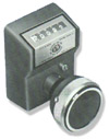
    Weight: 1.9lbs (.9Kg)
    Maximum Operating Temperature: 140 degrees F (60 degrees C)
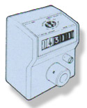
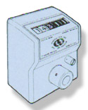
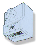
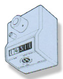
    Number Wheels: 5 with 1/4" (6.4mm) high numerals

    Installation Sequence
    1. Customer determines mounting (refer to Physical Dimensions to location non rotation holes.)
    2. Adjust unit to zero by rotating input shaft
    3. Slide instrument onto actuating shaft. Locate anti-rotation pin in non-rotation hole in mounting surface.
    4. Lock instrument to actuating shaft by securing set screw in input shaft.
    5. Use zero adjust screw to set desired initial reading.
    Special Handwheel Option

    Digital Position Indicator with an Optional Handwheel As an option, Mission Industries will provide a custom handwheel for the digital handwheel for the digital position indicator. Specify that preference when ordering. Handwheels mount to the customer's shaft.

    Mission Industries can add your company logo or function graphics to the face of the handwheel.


    Mission Industries, Inc.